Manufacturing guy-at-large.

Filtering by Tag: CAD

Share

Improved laser build

Added on by Spencer Wright.

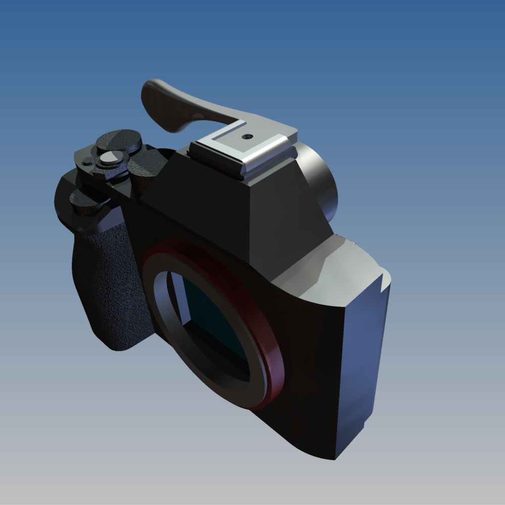
Learning new software is fun. This is me after a few hours playing with Materialise Magics 19 and SG+.

I've made a few modifications to the standard build:

  • Changed the surface selection angle to 50°. This build is set up for laser metal powder bed fusion (aka DMLS), which will print angles a bit below that, and it's very possible that 50° isn't optimal.
  • Changed the upper supports so that they're angled. In my last post you'll notice that if these are vertical, they'll rest on the bottom face of the cylinder. While that may be fine structurally, it means that I'd have that much more to clean up, and I think I'd rather have the supports go all the way down to the build plate instead. It's *possible* that this will reduce the amount of post processing necessary on the part - you'd need to run multiple builds with different configurations to be sure.

It's worth noting that this part is too far off the build plate right now - I'm still trying to get used to Magics' UI, and figured it didn't matter for now. I should probably also orient the part at a slight angle from vertical (see my recent post, here, for more details on this); again, I'll play with that a bit more later.

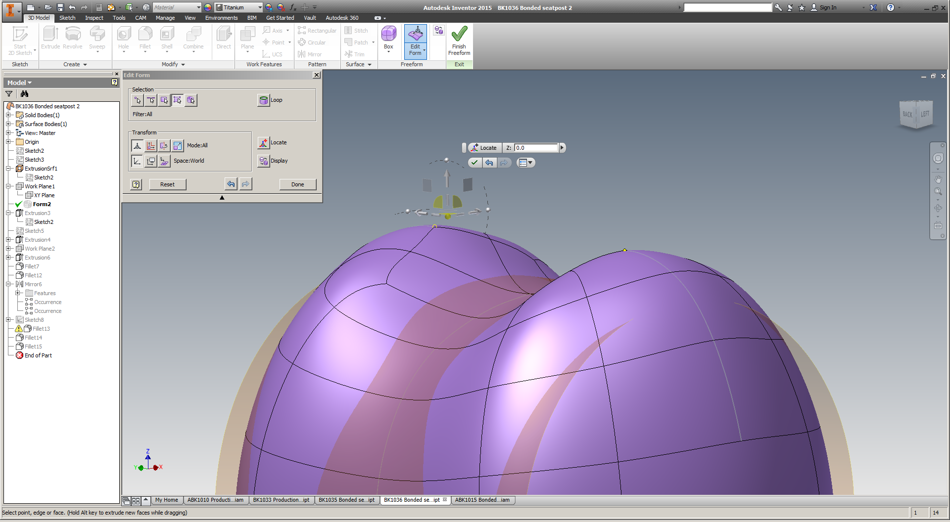
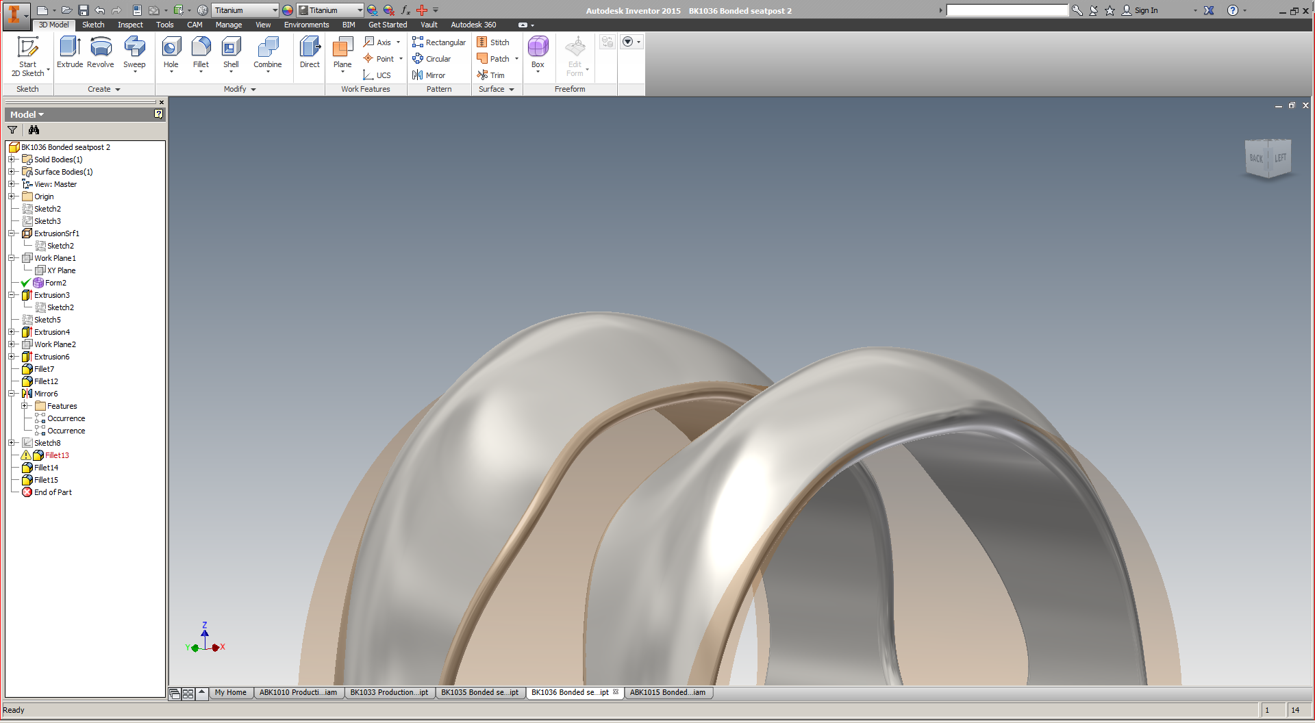
Oh, and I probably want to add additional reinforcements to the short ID, to make sure that it prints round. I'm looking at a few methods of doing this, most of which would require some work back in solid CAD (Inventor), or *possibly* some volumetric mesh generation software (like nTopology). 

I'm definitely still getting used to Magics' philosophical perspective on the additive process chain, too. I have some thoughts on what this is, but will play around more before I share them :)

Stay tuned.

Share

This week: Materialise Magics 19 and SG+

Added on by Spencer Wright.

Just a little teaser:

This week, in addition to the networking I'm doing (remember: I'm a free agent now, and directing my efforts toward finding the best path for myself in metal additive manufacturing), I'll be diving deep into Materialise Magics 19, the industry standard software for metal 3D printing build processing. I'm excited to learn more about its capabilities, and will share more later this week. I'll be spending most of my time working on orientations & support structures schemes for my titanium seatpost head, seen here in Magics' simulation of an EOS M280:

Magics bills itself as "The link between your CAD file and the printed part." It's used by OEMs and service bureaus alike to prepare design files to be printed - often times on the very machines that I've been building parts on (one, two) over the past year. In most cases, Magics imports an STL file. It then can be used for three big chunks of work:

  1. Fixing. In many cases the files that you import are broken in some way (edges not connected; faces oriented in the wrong direction), and can't be printed as is. Magics has a suite of tools that analyze and solve these problems.
  2. Editing. There are a variety of reasons why you'd want to edit a design before printing it, but probably the most common is that it won't fit in the build chamber of the machine it's being printed on. Magics offers tools that cut, hollow, thicken, perforate, extrude, label, boolean, and support parts and their features.
  3. Build prep. This is the part that I'm most interested in, as it directly affect the workflow that I've beed dealing with on my titanium parts. Here, the user selects the machine that the parts will be printed on. Then the parts are oriented physically within the build chamber, and an analysis is run to confirm that there are no part collisions that will affect the build.

Lastly - and of particular interest - is the SG+ module for support generation in metals. This would fall somewhere between (and across) numbers 3 and 4 above, and involves creating solid and mesh support structures that anchor the part to the build plate and provide thermal sinks to ensure a successful build. The SG+ module is a critical part of the metal 3D printing process chain today. It's used extensively across the industry, and engineers who are skilled at support generation are highly prized.

This week I'll be exploring these features (especially build prep and SG+) extensively; stay tuned for updates.

Share

Some quick modeling

Added on by Spencer Wright.

It's been a little while since I've played with this design, and I enjoyed getting back in to it. To be honest I'd like to spend a few days working on the model (I'd probably tear it down completely and start from scratch) but for now this is looking pretty nice.

Incidentally, T-splines continue to be *really* weird - and super cool. I really wish I had a more powerful computer; I suspect that would improve the experience significantly.

Share

Things that are on my plate right now

Added on by Spencer Wright.

Mostly for my own benefit & the sake of catharsis, here are the things that are consuming my attention over the past & for the next few months:

  • Planning my own wedding in October.
  • Having fun this summer.
  • Getting more exercise.
  • Writing a long blog post on the seatmast topper that I had printed (DMLS) by Layerwise, and then tested by EFBe
  • Writing a long blog post on the seatpost that I had printed (EBM) by Addaero.
  • Digging more into McMaster-Carr's iOS app, and comparing it to Amazon's recently rebranded Business offering.
  • Planning a sourcing trip to Shenzhen, where Zach and I will investigate a significant redesign of The Public Radio's speaker & mechanical assembly.
  • Getting more hands-on experience with metal powder bed fusion machines. Because there are none in the New York metropolitan area, this inevitably means traveling for a few days to somewhere where I have a friend in the industry.
  • Doing a deeper dive into the variety of design tools that are cropping up for additive manufacturing. This includes getting better at T-splines (Autodesk Inventor), working with topology optimization software (SolidThinking Inspire; Frustum Cloudmesh), and doing some experimenting with lattice structure generation (with nTopology).
  • Doing a deeper dive into build preparation software, namely Materialise Magics.
  • Building myself a real desk, preferably with a proper toolchest integrated into it. I also want 2x24" displays, a proper Windows computer for 3D design, a new Mac for daily use, and a place for both a Wilton "bullet" vise and my 12"x18" granite surface plate.
  • Writing a presentation on metal 3D printing that covers both my experiences over the past two years (a case study), and my broader observations on the industry. 
  • Getting said presentation accepted to an industry conference (likely either AMUG, RAPID, or Inside 3D Printing).

There are a few more longer-term things, but this is a pretty good list for now. 

Share

T-spline redesign

Added on by Spencer Wright.

As my seatmast topper has been moving towards destructive testing, I've been playing with a new seatpost design. This part would probably be EBM'd, and then bonded (with 3M DP420 or similar epoxy) to 27.2mm carbon fiber seatpost stock. I suspect that this design will be a bit more economical, and would work on a wider range of bicycles - including my own.

I've been pursuing the redesign in a few ways. First, I've been working with a few NYC folks to develop designs that incorporate either topology optimization, or lattice structures, or possibly both (more on this soon). Second, I got a trial license of SolidThinking Inspire, and have been using that to reduce mass within a design space that I set up in Inventor. And third, I took a crack at designing the part from scratch with T-splines in Inventor, which I *really* enjoy.

T-splines are a totally different way of approaching design, and they allow you to manually create organic looking structures. Once I've created the organic shape, I apply a bunch of features to it in Inventor's solid environment - allowing me to blend precise mechanical aspects within an otherwise fluid shape.

Ultimately, I'm optimistic that topology optimization & lattices will offer a less labor intensive workflow. T-splines are *awesome,* but editing them is a bit of an art, and I'd like to be able to redesign the part quickly to accommodate different saddle offsets, strength limits, seatpost diameters, etc.

Expect more progress soon :)

Share

Topper drawings

Added on by Spencer Wright.

While I've been writing a much longer post about DMLS, I made a couple of additional drawings of my topper. The longer post is coming soon, but I'll drop these here for now.

Share

Why not Github for mechanical design files

Added on by Spencer Wright.

I spoke today to Jon Placa @ ProtoExchange about how we're using Github on The Public Radio. In a followup email, he asked: "Is there any reason why you aren't using Github to host your actual design files (beyond gerbers)?" My reply:

No singular reason. But...
  • Only I work on our mechanical design, so there's no need to collaborate.
  • When I was collaborating on mechanical design (last job), I used Autodesk Vault - which is actually pretty good.
  • Mechanical design is even more fragmented - it's not as if me posting .ipt and .iam files on Github means they're really useful to anyone else, because maybe they're on Solidworks or an earlier version of Inventor - or, more likely still, on some consumer grade system.
That said, the original goal was to be open with all of it, and I would like to post those files there too - if only for posterity's sake.
Share

Diff Gifs

Added on by Spencer Wright.

Inspired by a tweet by Chris Loughnane, I decided to make a visual history of the EAGLE CAD commits that Zach & I have made to The Public Radio's Github since the beginning of December.

The schematic changes are pretty subtle:

The layout is more dramatic. Partly that's because of the shift to rectangular dev boards, but if you look closely you can see that a *lot* of stuff has moved around:

brd-development.gif

Incidentally, someone - Cadsoft? Github? - should make an automated way of generating these things. They're so useful!

Anyway. We'll be ordering another round of PCBs tomorrow. Fun!

Share

EAGLE Libraries on Github

Added on by Spencer Wright.

This has been *such* a PITA, but I think I just got The Public Radio's EAGLE libraries onto Github in a way that makes sense.

The goal: To have everyone be able to access all of the parts that we use on The Public Radio, no matter where they are or who created the package/symbol/part, by just syncing the Github repo.

Our Github page now has one active repo (Embedded_Hardware) - and two for firmware & firmware libraries that are mostly inactive for now. Within Embedded_Hardware are two big subdirectories (EAGLE_CAD and EAGLE_lbr), plus an ARCHIVE and a place for us to put production files (Gerbers, etc).

Within EAGLE_lbr, there is one EAGLE CAD library file - PR_Parts_Library.lbr. From now on, that will be the default library for all packages, symbols, and parts that we create or modify for use in The Public Radio.

In order to make this all work, you need to add the local directory that you sync to Github to your EAGLE Libraries search path. I keep our Github repositories at ~/Documents/The-Public-Radio, so I added :$HOME/Documents/The-Public-Radio/Embedded_Hardware/EAGLE_lbr to the end of my Libraries search path:

And now the EAGLE libraries show up just fine!

Lastly, I opened up our .brd and .sch and went through all the parts I had created. I drew the speaker, potentiometer, antenna hole and batteries. The .brd and .sch included copies of those parts that came from a library on my local disc, so first I had to find those parts and copy them to our new shared library. Then I went into the .brd and .sch and swapped the old versions of those parts for the new ones. 

Anyone else who's working on the project right now (that'd be Zach and Andy) can do the same with any of the footprints that they created. And anyone who's hoping to make their own (not sure why they would, but who am I to ask) can grab the entire Embedded_Hardware repository and modify packages to their heart's delight. If you do so and find a mistake we've made, please let me know - we're happy to take any pull requests that improve on our design!

Share

PR5006 -> PCBCart

Added on by Spencer Wright.

We pulled the trigger on this today.

Screen Shot 2014-02-10 at 2.49.45 AM.png

There are a lot of small-to-medium changes here, even from the last photos I posted. 

Screen Shot 2014-02-10 at 2.52.11 AM.png

On the top edge of the board:

  • Station tune LED circuit moved to the right. 
  • Cap on the tune circuit changed to thru-hole.
  • Trimpot package changed, moved outboard.
  • Tune circuit moved up and out, to get farther from the antenna trace.
  • Big thru-hole coupling capacitor on the battery, in the middle of the right side.
Screen Shot 2014-02-10 at 2.52.23 AM.png

On the bottom edge of the board:

  • Speaker traces reversed. I had originally routed negative and vise versa, but apparently that's not cool :/ Oh well.
  • Power routed along the perimeter of the board - no longer needs a via to get under the speaker traces.
  • Audio in was turned up and to the right for shorter traces & less interference with power.

We should have boards back in roughly two weeks. In the meantime we'll be hustling in like twenty ways so that we can be totally ready. Should be fun :)

Share

New Standards

Added on by Spencer Wright.

I've posted previously about my procurement process and elided a crucial detail: my part documentation for the past year has been pretty atrocious. Partly that's because I haven't been buying mostly 3D printed parts, which (when you buy from Shapeways et al) are documented only with STLs, but it's also because I haven't taken the time to set up my own drawing standards. Until yesterday.

This drawing is of the lid for The Public Radio. Depending on quantity it'll either be stamped or laser cut. I'd prefer stamped, but that's mostly because it'll be much less expensive at quantity - and I'd rather sell thousands of parts, not hundreds. 

The details of the drawing itself are rather mundane, but the title block and drawing format involved a number of weighty decisions. A few points:

  • I'm using an ISO A3 paper size. Because ISO is cool. 
  • I'm dimensioning in millimeters, and have default tolerances in millimeters too. This was a bit of a hurdle for me - I'm comfortable with metric dimensions but used to thinking of tolerances in thousandths of an inch - but I'm excited to be all (or mostly all) metric. Most of the tolerances here are three decimal places, which is basically the same at .13mm = .0051", is totally translatable for me. 
  • I'm using decimal points (instead of commas) between the ones column and the tenths column. Because Europe isn't right about everything.
  • I don't have any "approved by" field. Fuck standard title blocks, right?
  • "BREAK ALL SHARP EDGES." Yes.
  • Note: As I'm looking at this, I'm realizing that I should probably relax a number of these tolerances. Which often happens, the more you look at a drawing.
  • Revision tables. I start my drawings at "REV -", and then I increment alphabetically from there. This particular drawing was submitted to a few suppliers prior to this drawing standard, so I've incremented to "A" already... it's a little weird, but it works.
  • I'm not a huge fan of "TYP" or "typical," but in some cases it makes sense.
  • I'm using my part filename as a field in my title block. I considered separate boxes for part number and name, but I'm careful with filenames and this makes it easier.
  • I'm using an ISO time string (but with decimal delimiters) throughout. Because ISO is cool.  
  • I'm a little flippant in my title block (the "info, documentation & jokes" thing), but it's better than having to list my phone number.

Changes I should probably make:

  • I probably need a logo... or something. I don't know, a circle with a dot in it?
  • Line weights are off.
  • Do I really need to say what sheet it is? It's really only useful if you're documenting assemblies - at least with the simple parts I tend to design.
  • I guess I should be marking zones of the drawing space, but I've never done so in the past and never felt like I was missing anything.
  • I wish I could get rid of the file extension.

Overall I'm happy about this. Pretty fun.

Share

Working on The Public Radio v1.3

Added on by Spencer Wright.

Screenshots from both Zach and myself - we've swapped back and forth on layout duties.

The FM IC (Si4831) is at the top of the board; to its left is the tuning circuit and trimpot. On the right edge of the board is the power & volume pot, and on the bottom is the amplifier, and on the left is the antenna connector. The middle of the board has a big cutout for the speaker body to fit through; we'll solder the speaker terminals directly to the board.

I got a little cute with the restricts near the antenna trace, and ditto on the power trace along the left edge of the board :)

Meanwhile, I spent a little time today modeling the battery connectors in Inventor:

Finding nice through-hole AA battery connectors is *tough.* I'm hopeful about these - I think they'll hold the cell firmly but allow for easy removal too. The only downside is that they're not polar in any way, so we'll need to mark the PCB clearly to show which direction the batteries need to face.

Our antenna standoff is kind of exciting too. We're running a trace to a plated hole (with a *big* pad) on the PCB, and then fastening a male-female threaded standoff to the hole with a hex nut. The antenna itself will thread into the standoff, making it easy to remove/install for shipping, transportation, etc.

We're in the process now of getting quotes for a couple of custom pieces of hardware: the antenna, the knob, the potentiometer, and the speaker gasket. We've also gotten a few quotes for the lid, which will either be stamped or laser cut stainless steel. And when PCBcart comes back from Chinese New Year, we'll order a batch of new boards to get into the hands of our beta testers.

This is an exciting time in the project. Things are coming together quickly :)

Share

Public Radio Progress

Added on by Spencer Wright.

The last few days have been a bit of a whirlwind. 

First, we visited Todd to discuss some circuit layout concerns. On the way over we nabbed a cheap radio at RadioShack, and took it apart with Todd.. 

narrat1ve-1.jpg

What we found was really interesting. The device uses a different chip than we had been prototyping with, and as a result their circuit is *much* simpler. Our chip (Silicon Labs' Si4703) requires digital tuning, which we were accomplishing with a microcontroller. But RadioShack was using the Si4822, which is mechanically tuned. The result is drastic from a circuit standpoint - they no longer need a voltage regulator, or a microcontroller, or a bunch of additional passive components on the board. They're also in a better position re: noise on the board: an MCU (and a voltage regulator too) will produce a bunch of noise that might get on the antenna, affecting reception. RadioShack doesn't need to worry about this at all.

Over the past few weeks, we've been looking for just a breakthrough like this - a way of rethinking the problems we were dealing with. Our issue was that we were stuck conceiving this as an Arduino-descended product, which it doesn't need to be. 

public radio hammer nail-1.jpg

We also made a bit of progress reengineering the hardware layout of the board. Our new design (this is just the board layout, not the circuit schematic) will be significantly easier to assemble, program & service.

public radio hammer nail-2.jpg

We're also pretty sure we can shorten the antenna *significantly.* The mockup here shows a custom solid stainless steel antenna, 50mm long. I rather like it, and it's designed such that a longer telescopic antenna can be swapped in easily. 

short antenna round pcb full assy.jpg

Our PCB will now be circular, and we're soldering the potentiometer and speaker directly to the board. There will be a bunch of SMT stuff on the top (same side as the speaker & pot) and a battery back and trimpot (not shown) on the bottom.

I *really* like where this is headed. More updates soon. 

Share

The Public Radio v1.2

Added on by Spencer Wright.

Ordered yesterday from OSHPark. 

This board uses an Arduino Pro Mini, which can be programmed from either an FTDI cable or via an AVRISP (which we'll do to shorten powerup time). The rest of the circuit is all discrete components, mostly SMT. The whole thing mounts on the backside of a 3xAAA battery pack.

We should receive these boards around Valentine's day, and will be testing and iterating on them shortly afterwards.

Share

Seatpost collar

Added on by Spencer Wright.

After doing even more research on DMLS pricing (update soon), I played around a bit today with designing a seatpost collar. 

BK1026 Barrel nut Seatpost Clamp.jpg

The design here is pretty straightforward. I'm using fairly standard barrel nuts and a M5 bolt (I'll steal these from a Thomson collar I have laying around), and the part profile isn't trying to be innovative either.

I'm getting this printed in alumide (a mixture of nylon and aluminum) for an aesthetic/basic form/function mockup, and will look into pricing on the part too. I suspect that it could be relieved in a bunch of places still (to reduce build time & cost) but for now I don't care too much - I just want to get a functional stainless or titanium part on a bike ASAP.

Updates when Shapeways ships, probably before Valentine's day.